Project Development
As stated in our mission statement, our project aims to develop a prototype device that aids with object detection, sign reading, label reading, and produce a final ergonomic design concept for future development. To reach this final product, the team has developed a number of internal goals that attempt to integrate the iterative nature of human centred engineering with product development. Each developmental stage aims to progress the prototype based of learnings found in the previous review. The stages of development are as follows:

Proof of Concept
Internal Deadline: Week 1, Semester 2.
The proof of concept acts as an initial trial run to ensure that lower-level individual software components are correctly interacting within the overarching systems architecture. In simple terms, the PoC tests how the individual parts of the device talk with one another and identify any potential interruptions or failure in the communication channel. It is important to note that the PoC does not focus on the hardware or ergonomics of the device, but rather tests the feasibility of the idea before further time and resource investment.
The test user will be equipped with a smartphone that is attached to their chest to capture live stream video footage and a pair of Bluetooth headphones which the device will use to communicate with the user. Video footage is streamed from the smartphone device to a laptop carried by a team member directly behind the user to ensure the two devices remain within range. Using WIFI connection the laptop captures necessary frames from the video footage for image processing (client side) before sending the frame to an online server (server side) where a response is generated and sent back to the client to be relayed to the subject.
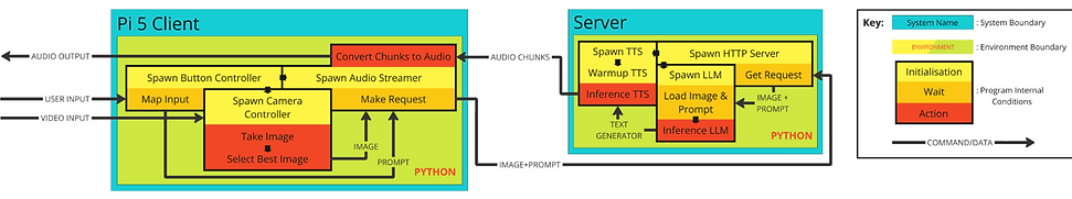
Image Description - The image showcases the system architecture of the Ver device. The flow diagram depicts each of the software components and functions running within the device. On the far right is a key which describes the four key features. This includes: Blue represents system boundary, green represents environment boundary, yellow, orange and red are all included in the internal program conditions while the black line connecting all sections represents the direction/flow of the command/data.
For the purpose of the PoC, the subject will interact with the device by selecting one of the twelve pre-set prompts. This will require the subject to talk with the team to determine which prompt would be the most useful in any given situation. The 12 pre-set prompts used during testing were as follows:
-
Describe what can be seen in 10 words. Use only Natural language.
-
Describe what can be seen in 20 words. Use only Natural language.
-
Describe what can be seen in 30 words. Use only Natural language.
-
Describe what can be seen in 40 words. Use only Natural language.
-
Describe the signs that can be seen in as few words as possible. Use only Natural language.
-
Describe the signs that can be seen in as few words as possible. Use only Natural language. If no signs can be seen reply as such.
-
Describe the signs that can be seen in as few words as possible. Use only Natural language. If no signs can be seen reply with ‘There are no signs that can be seen A T M’
-
Describe the colours that can be seen. Use only Natural language. 40 words maximum.
-
What locations are listed on the sign. Use only Natural language.
-
What am I pointing at, reply in 10 words?
-
What am I holding, reply in 10 words?
-
Where are the bananas, reply using clockface coordinates with 10 o’clock being leftmost and 2 o’clock being rightmost.
Minimum Viable Product (MVP)
Internal Deadline: Audit 3 - Week 5, Semester 2.
The purpose of the Minimum Viable Product is to produce a prototype that, on paper, satisfies all project requirements. The MVP incorporates the software developed for PoC into basic hardware components such as a processing board and compatible camera. This allows the team to test system integration with the selected hardware components and gain valuable feedback on a tangible design.
The MVP was scheduled for presentation in Audit 3 as evidence of the team progression but will not be tested on end users. The MVP made several developments from the PoC prototype, these included:

Concept 1
Deadline: Stakeholder Testing - Teaching Break Week 2, Semester 2.
Concept 1 is an initial prototype of the selected user design, incorporating device hardware developed in the MVP, with the wearable user component. Prior to concept 1, the team has focused on developing a portable, working prototype to test concept feasibility and system integration. With MVP confirming the successful integration of hardware and software, the next step is integrating the design into a well disguised, aesthetically pleasing, wearable design.
Taking the stakeholder needs and hardware requirements into consideration, the team determined three potential wearable designs. These are as follows:
-
Pocket attachment: all-inclusive power, processing unit and camera unit design that could be worn on the user's apparel. The device could either be pinned onto their jacket or slotted into a breast pocket.
-
Integrated bag design: The integrated bag design aims to reduce the weight and size concerns by storing the processing unit and power supply in a bag segment. The camera and button components will be located on the bag strap across the user's chest and internally wired back into the bag to transmit data.
-
Camera pin: Loosely modelled off the Samsung Insight. This design has been created to demonstrate a desirable product outcome based off the stakeholder requirements. It is designed to be small, discrete, lightweight, intuitive to use and easy to attach to use clothing.
While the camera pin design would be the most optimal approach at meeting our stakeholder needs and project requirements, with limited time and resources the team decided to further develop the integrated bag design. The integrated bag design consists of two main compartments. The first being the camera module, a small rectangular box that sits along the bag strap which includes the device camera and the user input buttons. The second is the processing and power supply unit which is located within the body of the bag. Wires between the camera and button inputs are fed down the strap to transfer information for processing. The image below depicts the preliminary design sketches used to flesh out this concept.

Stage 3 developments can be summarised into the following:
-
Hardware and casings from MVP were re-designed to be incorporated into a cross-body bag.
-
New, extended wiring allows for camera module to be place at any position along bag strap to best suit user comfort.
-
Development of the “chat” function to offers users the opportunity to ask tailored questions to the device.
Moving on from concept 1, the team at project Ver will take the recommendations and learnings from user testing to further develop the design to be included in the final design.